In this article, I will explain how to make yourself a DIY 12V LiFePO4 battery. The chemistry we are going to be using is LiFePO4 with prismatic cells. I will share where I bought the cells and the BMS I use. Let’s get started!

Cost of a DIY LiFePO4 Battery
Making a DIY battery has some advantages. One of those advantages is the cost. You will get a cheaper price and you are in control of the components.
These are the costs involved in building the battery:
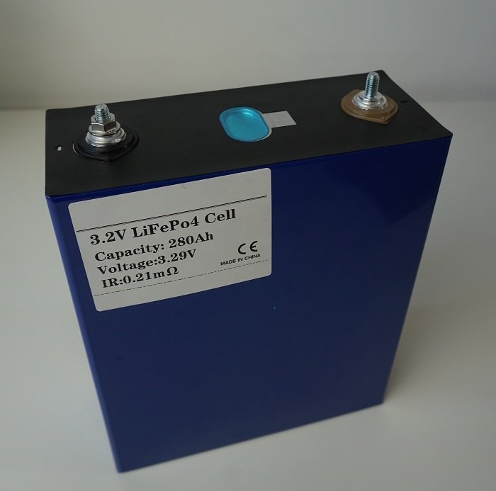
- Battery cells: 4x280Ah 3.2V EVE cells for a total of $576
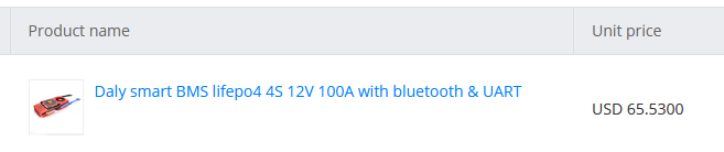
- BMS: 100A Daly BMS 12V 4s for a total of $65.5

The total cost of the battery is $641, which equals $0.19/wh. A good quality battery that I recommend in my lithium battery buying guide costs $0.29/wh.
These components were bought a while ago. Expect the prices to be 10% more.
Battery Composition
This battery pack will be used as a backup to feed a laptop and a phone when the grid is down. I have chosen four LiFePO4 cells (lithium iron phosphate) for this project. Every cell is 3.2V and has a capacity of 280Ah. If we put 4 of them in series, we get a nominal battery voltage of 12.8Volts and a capacity of 280Ah. The total capacity of this pack is:
12V x 280Ah = 3,360Wh
This can power my laptop for:
3,360Wh / 50W = 67 hours
Battery Management System
If you put these four cells together and start using them, one cell can be 3.1V, and the other can be at 3V. To use the battery’s full capacity, we have to keep every cell at the same voltage. We can do this by including a battery management system or a BMS. I have chosen the daily BMS. The BMS for my application is a 12V 4Cell 100 Amp version. This means that it will suit my 12V battery with four cells.
The maximum current I can draw from the battery will be 100 amps, the maximum allowable current for a long lifespan (watch my video about c-rate). My laptop charger is rated at 50W and the inverter will draw about 15W of idle power (read my inverter buying guide). Knowing this, we can calculate the maximum current we will draw from the battery with our predetermined loads:
50W+15W = 65W
65W/12V=5.4A
Now 5.4A is not a lot of power. The current will increase if I decide to charge more items or even power a fridge. That’s why we need to size our BMS according to the size of the inverter. I have a 600W inverter.
600W/12V=50A
We can draw a maximum of 50A through the BMS. We can also power some extra DC loads, but they should not exceed 50A.
Getting to work
In this part, we will start the practical steps from receiving the battery to adding and testing the BMS.
Checking the batteries
Once the batteries have arrived, I will check the voltage of the batteries. While the voltage at this stage doesn’t mean much, it’s good to check them and make some notes. I numbered them and put their state of charge in an Excel file.
When we charge these cells together, they each can have a different voltage. That’s why we must do an initial balancing before the BMS does the job for us. The best way of doing this is to charge the batteries up to 100%. That means that every cell has to reach 3.6V. If we use an adjustable power supply, we can achieve this. I will be using a 10 amp power supply.
You can charge each cell individually or put the cells in parallel and charge them at the same time. When the cells are in parallel, they will have the same voltage. It will be quicker this way, but you will have to add a wire or busbar to connect every cell.

Adding the Battery Management System
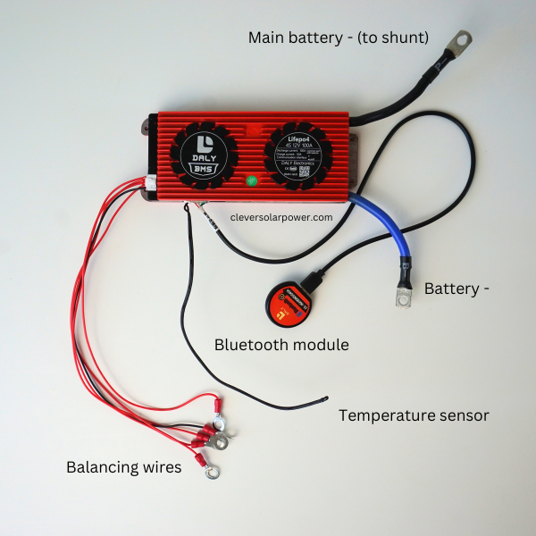
Now we will add the BMS to the battery. The daily BMS will have two big leads which will act as the negative battery post. The black one will connect to the main battery negative and the other wire will become your new negative battery post.
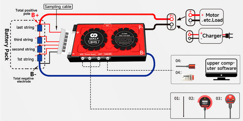
The five other wires will go to every cell negative and positive cell.
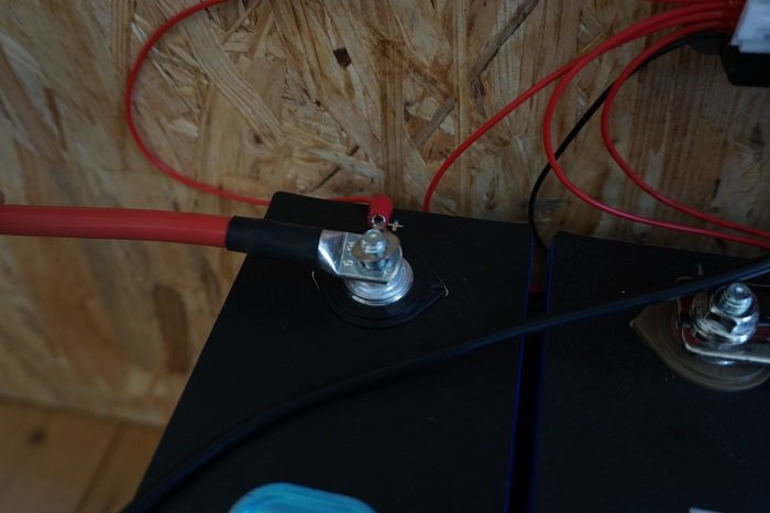
Important to know is that your big lugs or busbars go first on the battery cell terminal, then the balancing wires. This will ensure that the current-carrying conductors have a flush connection with the cell posts.
Testing and some critical notes
Now that we have finished building the battery, we can connect it to a load.
Fuse: To calculate your fuse size, refer to my guide about choosing the correct fuse size. I used an NH00 fuse, similar to a class-T fuse. I use these because they are widely available in Europe and are cheaper than Class-T.
Wire thickness: To calculate the wire thickness, refer to my guide about selecting wire size. I use 16mm² for my 100A max draw.
Method of connecting lugs on battery posts: First, you need quality lugs. Quality lugs will cost you around $1 per lug or more. Do not cheap out on lugs. It is a real hazard. You need to add the lugs which carry the largest current first, then add the lugs with the least amount of current next. You can see that the main battery cable is first followed by the balancing wire from the BMS. See this in the following image:
Shunt: I recommend adding a shunt on the negative post after the BMS. This is to monitor the capacity of your battery. Read more about shunts here and my recommended battery monitor here.
Safety: Always wear safety glasses when working with batteries and electricity in general. Also, insulate your tools.
[custom-related-posts title=”Related Posts” none_text=”None found” order_by=”title” order=”ASC”]
I’m an off-grid enthusiast. I created this website to give clear and straight-to-the-point advice about solar power. I’m also the author of the book ‘Off-grid solar power simplified‘. Read more about me on my about page, check out my Youtube channel, or send me a message.
Great diy information. thank you
Can LifePo single cells be orientated vertically positive end down in a DIY battery ??
No, they should not be placed upside down. they can be sideways.