This is a complete guide on calculating your off grid tiny house solar power system.
We are going to discuss:
- Load analysis
- Selecting Components
- Drawing the schematic
- Calculating the fuses and wires
If you want me to size and draw your system, view my service here.
Grab a cup of tea because this will be a long one!
Step 1: Load Analysis
Before we order any components, we need to do a load analysis. Building a system without a load analysis is like throwing darts at the target with a blindfold.

In the following image, you will see my custom load analysis of a realistic tiny house. I will do the explanation below the image. It consists of a few household appliances like:
- Lights
- Water pump
- Microwave
- Fridge
- Laptop
- Inverter losses
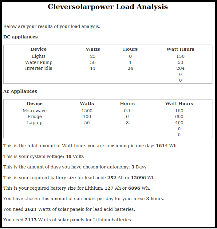
As you can see, you need to know the device’s power and the time you will be using it every day. If we add these up, we become a number in watt-hours. That will be the amount of energy you will consume in one day.
I recommend using a 48 Volt battery because the charge controller and wiring will be cheaper.
I have chosen three days of autonomy, meaning you can run your loads without sun for three days.
Now the calculator will do its job and suggest a 48 volt, 127 Ah battery or 6,000 watt-hours.
We need to recharge the battery in one day to have a properly sized system. In most places, the average sun hours is three. This depends on your location. It’s best to use the worst-case scenario for this. So choose the winter because then there is the least amount of sun hours.
The calculator tells us we need 2,000W of solar power to recharge our battery in one day if we use a lithium battery. Since the roof area of the tiny house is limited, we will put five 200W panels on it. We will add another five 200W panels on the ground. 200W panels are still easy to carry. If we use the more price-efficient 400W panels, carrying them around will be a real chore.
Step 2: Selecting Components
I recommend selecting the components instead of using ecoflow, yeti, or other solar generators. Doing this custom will save you a lot of money and have a better, more customizable system.
Solar Panels
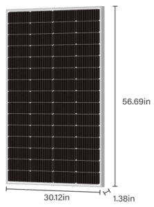
We will 220W panels from Newpowa. Why 220W panels, you might ask? Using 400W panels would be more cost-effective, but it’s hard to find panels that are shipped per piece. It’s either per 10 pieces or per pallet.
Another reason is that 220W panels are still portable for a ground mount system. Imagine you are moving your tiny house (if it’s on a trailer), then setting up additional panels would be easier and less cumbersome than 400W panels.
Read my informational articles:
- Solar panels series or parallel (opens in new tab)
- How to wire solar panels for shading (opens in new tab)
- Best tilt angle for solar panels (opens in new tab)
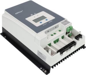
Charge Controller
From our load analysis, we need 2000W of solar to charge the battery in one day. Let’s find out how many solar panels we can put in one series string.
The 220W solar panel has a typical Voc (volt open circuit) of 20.52 Volts. We need to multiply that by 1.25 for safety margins. That means we can only have 4 panels in series.
20.52 Voc * 1.25 * 5 Panels = 128 Volts
Let’s have two strings of 5 panels each for 10 panels. This is called a 5S2P system (5 series, 2 parallel).
The charging current of the solar panels will be decided by the power of the panels.
2200W/48Volts=45.8A*1.25=57.3A
We will use the Epever 60A 150V 48V 6415AN charge controller.
Read more about charge controllers:
- PWM vs MPPT (opens in new tab)
- How does a solar charge controller work? (opens in new tab)
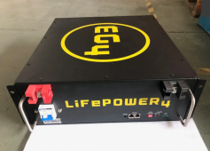
Battery
For the battery, we will choose three server rack lithium batteries. These are the most cost-effective battery solution. EG4 is now the best. Each battery is 5kwh. This is 1kWh short of our required capacity. Since we have over-paneled the solar panels, we can also reduce the need for another battery.
Inverter

Looking at the load analysis, we need a 2,000W inverter. We will choose the MultiPlus 48/2000/25-50. This inverter/charger from Victron is ideal for our use. It will convert the power from the battery to AC power.
It will also take shore power and charge the battery if needed with 25Amps. The inverter can also take a generator on the AC-in. The idle consumption of this inverter/charger is 11W. This is very low compared to other inverters or hybrid inverters with a stand-by load of 70W.
DC converter 48-12V
To power some 12V loads like lights and a water pump, we need 12V. Therefore we will use a small DC-to-DC converter. I have chosen for a 340W 48 to 12V DC to DC converter.
Shunt
To read the battery status, we will need a shunt to measure the power that goes in and out of the battery. There is no need for an expensive Victron shunt here. A simple shunt that works great is this one.
Wires and fuses
We will discuss wires and fuses in the schematic, which I will discuss next.
Step 3: Drawing the Schematic
Here is the schematic of the system. We will start with solar panels. We have chosen two strings of 5 panels for a total of 10 panels that deliver a total of 2.2Kw. This is the most economical way to wire the solar panels.
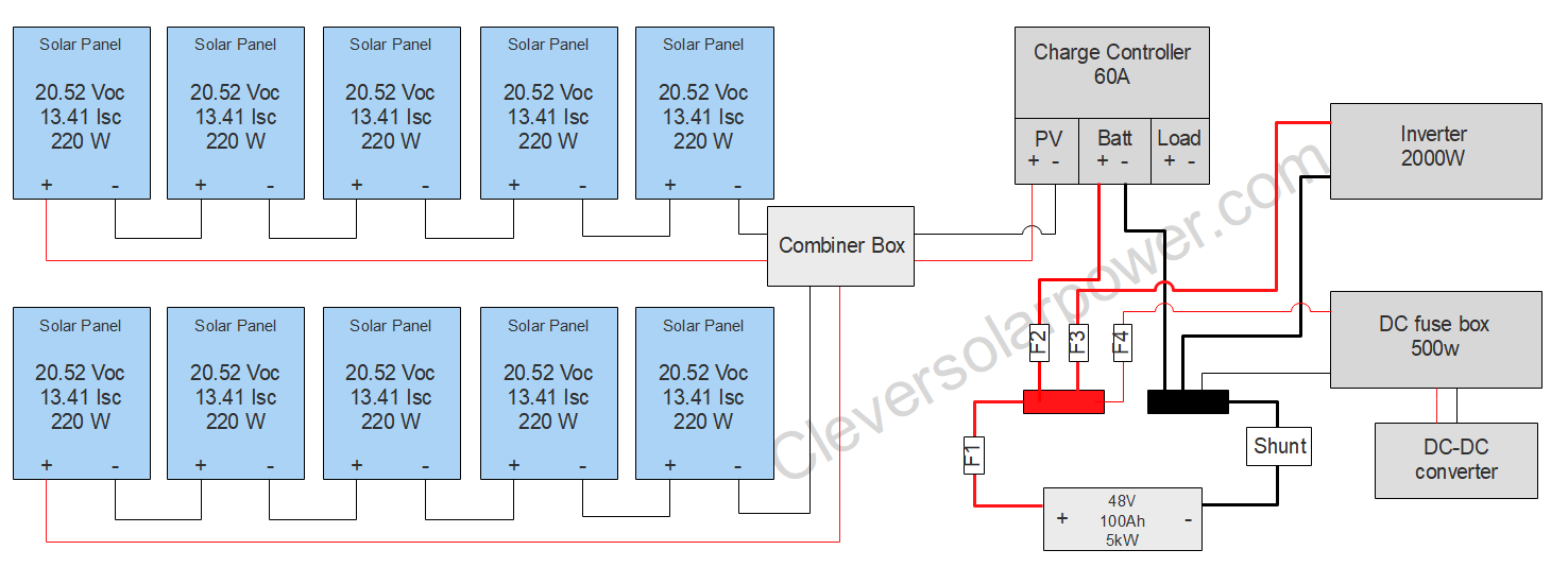
The solar panels will go into a combiner box where every series string is fused and one main disconnect breaker. From here, there will be two wires going to the input of the charge controller.
From the charge controller, the wires will go to a busbar where the wires are distributed. In between, a fuse (F2) will protect the wire from the charge controller to the busbar.
From the busbar we will go to the battery. Here is also a fuse called F1 to protect the wire. The negative pole from the battery will go to a shunt to measure the state of charge of the battery. It will display how much % is left in the battery.
From the busbar there will be wires going to the inverter with a fuse (F3) and to the DC fuse box with a fuse (F4).
Step 4: Calculate Wire Size and Fuses
Solar panel wires to the charge controller
The voltage from the series string is:
Vmp*amount of panels in series string= 17.52V*5panels=87.6V
The current will be 13.41A. This is the Isc (current short circuit). In the image below, you can see a voltage drop calculation. To have a less than 3% voltage drop we will need a 14AWG (2.5mm²)wire. But there are no 14AWG wires with MC-4 connectors, so we will use a 12AWG (4mm²) wire. This is calculated for a 30ft length. Alternatively, you can make your own DIY MC-4 cable.

The two series strings will be combined in the combiner box. We must calculate the wire from the combiner box to the charge controller. You can have the combiner box inside your tiny house or outside. I will use a length of 10ft for this cable. In the next calculation, the voltage stays the same, but the current doubles because the current gets added up in parallel.
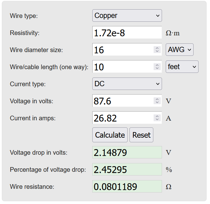
We can see that we only need a 16AWG (1.5mm²) wire. But a 16AWG wire cannot handle 26.82Amps. Instead of using the voltage drop method, we need to calculate the thickness of the wire based on the current capacity instead of distance.
26.82A * 1.25= 33.5A
A wire that can carry 33.5Amps is a 10AWG (6mm²) wire rated at 90°C insulation.
We don’t use a parallel branch connector in this system because it’s limited to 20 Amps of current.
Fuse sizes for the individual series strings are 15Amps. The breaker size can range from 30 to 60amps because the current through the wire is already protected by the previous fuses. The breaker solely acts as a cut-off switch to isolate the solar from the system. This is required by law.
Charge controller to the busbar
The charge controller can deliver a maximum of 60 Amps to the battery. This cable needs to be held as short as possible. We need to apply a safety factor of 1.25 or 125% of the nominal current.
60A * 1.25 = 75A
A wire that can carry 75Amps is 6AWG (16mm²) with an insulation temperature of 90°C. However, we need to fuse the wire with a 75amp fuse. But that is not possible because there is no 75A fuse. The closest fuse is 80Amps, but running 80amps through a 6AWG wire is impossible. So we have to use 4AWG (25mm²) with an 80Amp fuse.
Busbar to battery
The total load is 2000W from the inverter + 500W from the DC fuse box. In total we have 2500Watts of power going through this wire at 48V.
2500W/48V=52A * 1.25 = 65Amps.
A wire that can carry 65Amps is 6AWG (16mm²) wire. We can use a 70Amps fuse because the maximum current a 6AWG wire can carry is 75Amps.
Busbar to inverter
2000W/48V= 41.6A * 1.25 = 52Amps.
A wire suited for 52Amps is 8AWG (10mm²). The maximum current an 8AWG wire can carry is 55Amps. We should use a 55Amp fuse, but there is no 55Amp fuse. So we will use a 6AWG wire with a 60amp fuse. The max current a 6AWG wire can carry is 75amps.
Busbar to DC fuse box
500W/48V=10.4*1.25= 13Amps
A wire suited for 13 Amps is 14AWG (1.5mm²). 14AWG can carry 25Amps. So we need a 20Amp fuse.
Conclusion
There you go!
Here you have a blueprint of a solar system for a tiny house. You can add or remove items as you wish. Make sure the wires and fuses are still correct.
If you want me to draw a system for you, then checkout my service here.
If you have questions or suggestions, feel free to leave a comment below, and I will get to it as soon as possible.

I’m an off-grid enthusiast. I created this website to give clear and straight-to-the-point advice about solar power. I’m also the author of the book ‘Off-grid solar power simplified‘. Read more about me on my about page, check out my Youtube channel, or send me a message.