Here you are, asking yourself the question, Can I charge a battery bank with two charge controllers?
Here are some reasons why you might want to add another charge controller:
- You want to add more solar panels to your system.
- You want to add a panel with a different specification than the one you already got.
- You want to separate panels from each other because they receive shade at different times of the day.
Now your next question might be: do they need to communicate with each other?
How do Charge Controllers Interact With Each Other?
Charge controllers sense the internal resistance of a battery and send their current to the battery terminals based on the resistance of the battery. If the battery is at a low state of charge, the resistance will be low and the charge controller will charge in bulk mode (depending on the battery type).
If the resistance increases, the charging current will decrease because the battery is almost full.
If two or more charge controllers charge the same battery, the battery will be charged quicker. The multiple charge controllers will not compete with each other because they all sense the same internal resistance of the battery. If charge controller A puts in 100Watts, charge controller B will also put in 100Watts into the battery.
When you program your charge controller you can add the cutoff voltage in the software. That means if your battery reaches a pre-defined voltage, it will stop charging. You can tell charge controller A to charge to 12 volts and charge controller B to charge to 12.8 volts. This is not needed but is good to know because one charge controller might stop charging if it reaches that point, and you will be wondering why that is. Also, if the wires of charge controller A are a bit longer, it might enter float mode earlier than charge controller B because of the voltage drop (increased resistance).
If the charging current becomes too high, the internal resistance of the battery will change because of the heat generated. The charge controllers will then reduce their power input to the battery.
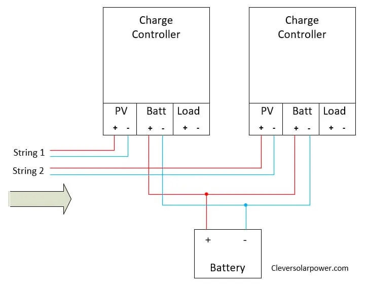
Wiring Two Strings to Two Charge Controllers
In this example, there are two strings or arrays of solar panels that go to every charge controller. This setup is ideal if you have multiple solar panels that do not have the same rating. Refer to the article about series and parallel wiring solar panels if you want to know more about how to wire your panels, or check out my video.
You can also use this kind of setup on a boat. If one charge controller is in the shade of a sail, but the other is in full sunshine, the sunny panel will still deliver its max power. The shaded panel will deliver reduced power. This is very similar to wiring your panels in parallel.
You can either use PWM or MPPT charge controllers for this. The kind of charge controller you have doesn’t matter. You can use a PWM and an MPPT to charge a battery.
Synchronizing Multiple Charge Controllers
If you are using two or more charge controllers they do not need to be able to communicate with each other.
There might be a problem with flooded lead-acid batteries where they equalize every month. If you have multiple charge controllers attached to the battery bank they equalize more frequently, Which is not good for the battery. You need to turn off the equalizing function on the other charge controllers so you only have one charge controller performing the equalize function.
Some models are able to communicate with each other like the Victron BlueSolar and SmartSolar models. The communication happens with the built-in Bluetooth module for the SmartSolar model. For larger systems, they recommend using the VE.can port.
The reason for communication between charge controllers is so that only one charge controller will balance the cells, not all of them (only with lead-acid).
Both charge controllers will deliver their maximum amount of current to the battery.
I guarantee this guide will save you $100s on buying the right components by having a good design and sizing.
You can get the book for a reasonable price on amazon
Maximum Charge Current
Lead-acid batteries can only be charged at a low C-rate (0.2xAh capacity). while Lithium batteries can be charged at a higher C-rate (1xAh capacity).
For example, you can efficiently charge a 100Ah lead-acid battery with a current of 20Amps, or a 100Ah lithium battery with 100Amps.
You need to take this into consideration. If the charging current will be higher than those rates, the energy will be dissipated as heat or the BMS (battery management system) will limit the current going in the battery. Make sure your battery capacity (Ah) is high enough to accommodate another charge controller.
Can I use a multiple input charge controller?
Many people find it attractive to have one charge controller to which they can connect mixed solar panels. However, this is not a good idea for redundancy. What happens if the one device that charges everything is broken? Another problem is availability. Most of the time it will be hard to find one according to your specifications. Therefore it’s better to have multiple separate charge controllers.
Can I use different size and brand charge controllers in parallel?
Yes, as long as they have the same settings. These are:
- Battery voltage
- Battery profile (lead-acid, AGM, Lithium)
Can I use PWM and MPPT together?
Yes. It’s best to set both PWM and MPPT controllers to the same voltages. So they both work at the same time. If one is set at a lower voltage, the second one will keep charging. While it will not hurt your batteries, it’s best to set the same charging voltages.
Can you run 2 MPPT controllers together?
Yes. You can run two or more MPPT charge controllers together as we discussed in the article.
Conclusion
You can wire multiple charge controllers in parallel to support an expanding solar system. You do not need to have charge controllers that are able to communicate with each other but you should only enable the equalizing function in one of them if you have flooded lead-acid batteries.
If you want to watch a video about this article, you can do so here:
That’s how you connect 2 charge controllers 1 battery bank. Hope this article was helpful!
[custom-related-posts title=”Related Posts” none_text=”” order_by=”title” order=”ASC”]
I’m an off-grid enthusiast. I created this website to give clear and straight-to-the-point advice about solar power. I’m also the author of the book ‘Off-grid solar power simplified‘. Read more about me on my about page, check out my Youtube channel, or send me a message.
Thanks!
Your work is appreciated. Solar is my passion. Off-Grid Solar Power plants. I bought the book and enjoy reading this online too.
Looking forward to learning more.
Thank you Julio! I appreciate it.
thank you Nick for information of solar Off grid
Very helpful thanks
Thank you
Solar panel array to multiple charge controllers (parallel) and one battery bank. Just about every other article I have read about this states that it is not a good idea to do this and that each PV array should be connected to each MPPT controller independtly. I was looking to use two identical solar controllers in parallel with one PV array, but I am slightly confused as to weather this will work OK?
Regards,
Graeme
Hello Graeme.
This is not the most effective method to wire your solar panels to the charge controller. If the whole PV array is facing the same direction, this method will work. The problem is when something happens to the array. If one solar panel gets damaged or shaded, it will influence the whole power output of the array, which will affect performance. It’s not the most efficient way, but it will work. I recommend wiring it like the second image. I have updated the article too.
Second image?
I only see one image (“connecting 2 solar charge controllers to 1 battery”).
Check image ‘diagram on connecting 2 solar charge controllers to 1 battery’ this is the correct way.
Fascinating and well explained !
I’m thinking of the following and not sure if it’s a workable idea or not.
This would be to harvest as much daylight during winter … (summer supply/consumption should be easily met). House only has 4x250w at the moment and cannot meet very miserly use in winter. 24v system, large lead acid forklift battery.
Planned … barn roof installation.
South facing: 2 x 370w in series plus the same in parallel (4 panels total) with 40a MPPT
West facing: the same as above
Both outputs of the MPPT controllers to feed one pair of heavy duty copper cables running to the battery 16m away.
Arrays planned for redundancy and resilience with panels being manually isolated in extreme sunlight (if needed) or switched to a separate battery bank (if the future requires it). Potentially Heath Robinson but truly modular in scope.
Would this system seem plausible ?
kind regards
Duncan
We have to know that light intensity affects the amperage, and temperature affects the voltage. Knowing this, we can predict that the two panels facing south would deliver a higher current than those facing west. This means that those two series strings should be placed in parallel to make a hybrid connection, just like you said. Because in parallel connections, the amps add up while voltage stays the same. Make sure the voltage drop stays under 3% for those 16-meter cables. Place your charge controller as close to the battery as possible. Check voltage drop video here: https://www.youtube.com/watch?v=d9ByUjphO6A&ab_channel=cleversolarpower
Hi Nick,
I first want to commend you on probably the finest book (Off-Grid Solar Power Simplified) I have come across so far on the subject of Solar Power Systems. It has been extremely helpful to have a complicated subject explained probably as best as one could explain it. Thank you
One question I have wondered and was not answered to my satisfaction (by a company tech). I will soon have 8 X 100 Watt Renogy mono panels to a 60 Amp MPPT Renogy Charge Controller and using 540 Ah Lithium battery bank (I am going to make my own Lithium battery from online community you suggested). I asked if there was some way I could add a future wind mill. I was told they didn’t have provision for multiple power inputs, therefore not possible. But reading your article above it sounds like I can add a wind mill to a second charge controller (sized for the wind mill of course, I assume it doesn’t need to be the same size as my other charge controller, but it will be an MPPT) and then wire both charge controllers in parrallel to the battery? How does that sound? And I have a creek that runs outside my window. My goal also was to have some kind of micro-hydro someday. Therefore add another charge controller for that and wire in parallel to same connections as others. I believe I read somewhere in your writtings it would be best to have all charge controller cables the same length? And since I am using Lithium I don’t have to worry about changing any settings (like turning off equalizing, or setting voltage cutoffs to different levels, etc.). Thank you for your help
Hello Andy, Thank you for your compliment about the book. I really appreciate that. I’m sorry for the late reply, I was on vacation.
Coming back to your question, it’s not a problem to have multiple charge controllers in parallel charging your battery bank. The cables from the charge controller to the battery bank can have different lengths.
The thing you need to make sure of is the maximum charge current that your battery bank is able to absorb. Let’s say your DIY LiFePO4 battery can absorb a maximum current of 100 amps, then all your charge controllers combined shouldn’t deliver more than 100 amps, otherwise, your BMS will shut down.
What voltage will your system be?
Dear Nick,
First of all thank you very much for your informative and helpful writing.
I would appreciate, if you can share your thoughts on my subject as explained below:
I installed an Off-Grid Solar, Wind and Battery connected parallel to each other a month ago. Solar panels(3.6kWp) are connected to Growatt SPF5000 off-grid inverter. The Wind turbine(3.3kW at 14m/s) has its own Charge Controller with 48Vdc output. The battery is also from Growatt with 3300Wh capacity, LiFePO4 type, communicated via CAN with the Solar Off-Grid Inverter. The Battery, Wind Charge Controller and Off-Grid Solar Inverter outputs are connected in parallel to a 48Vdc busbar in a panelboard. But so far no loads have been connected to the system. Only the internal consumptions of the devices use energy from the battery.
I have been monitoring the behavior of the system for a few days through the monitoring system of the inverter and observed that the Wind Charge Controller is not charging the battery. In a normal day time, when the battery goes down to %95 SOC level, It is charged back again to %100 SOC with the Solar inverter. As the PV Modules are not generating energy at night, the level of the battery is going down to around %70 SOC level (due to internal consumption of the battery). When the Solar Energy becomes available in the early morning, the battery starts being charged back to %100 SOC. I am trying to find out, why the battery is not being charged wind turbine charge controller? I might be hard for you to figure out system in detail, but incase you need further detail, I can share.
Best regards,
Alper
Hello Alper,
You have explained your system well, I will try to give you a few tips.
– Can you measure the amps going from your wind charge controller to the busbar?
– The internal consumption of the battery is very low. If you go from a 100% to 70% SOC without appliances on, there is something wrong.
– Could it be that the charging/discharging system voltages are different on the wind turbine than the growatt hybrid?
– it could be that the wind turbine has no chance of charging up the battery because it doesn’t reach a low enough voltage.
– Is the wind controller suited for LiFePO4 batteries?
Hi There,
I appreciate this so much! I’m using this set up to wire my solar panels to 2 Epever MPPT charge controllers. Since purchasing the first charge controller, I’ve changed my setup considerably and needed a second.
Like the charge controllers in your diagram, I chose this controller because I could wire the load directly to it and control the battery discharge this way. But now I’m wondering, how do I wire the load if I have 2 charge controllers with this capability and 1 battery?
I hope this isn’t the silliest question. Thank you so much for your time.
Clare
Hello Clare, There are no silly questions, only silly answers and I hope mine isn’t one of them.
– I do not recommend connecting your load to the charge controller. Instead, I recommend connecting your loads to the main battery terminals. Especially if you have a big setup like yours. You need to use a low voltage disconnect between the battery and your load, this will work the same way as your charge controller. The difference is that you can draw more amps because the output on the charge controller is limited.
– If you still use the load terminals on the charge controller, then using one charge controller is fine if it meets your current demand. The current on these outputs is severely limited.
Hope this helps.
Hi Nick,
Thanks for the informative web pages! Good reading.
Similar to the question of using multiple charge controllers, I was wondering about hooking a small battery charger or trickle charger to a battery bank that is also charged by solar panels and a charge controller.
Specifically, on my off-grid studio I have a 4×100 watt panels, with single 12V 30a solar charge controller connected to a small battery bank (3x 100ah AGM batteries in parallel). After continuous rainy days the batteries get depleted because there simply isn’t enough sun. However, the studio is close enough to my house that I could run an extension cord if need be.
Can I hook a small auto battery smart-charger to the batteries, maybe a trickle charger (5a or less), to work in tandem with the solar charger? Just to keep the batteries topped off during bad weather. Would this damage the solar charger or would they play well together?
Thanks!
Hello Glenn, Ideally you need a low voltage disconnect so the batteries don’t get depleted under a certain voltage. as soon as there is sun, the batteries get charged again.
You can use your extension cable to run your appliances this helps reduce the cycles on your battery. But adding a trickle charger to a battery bank wouldnt be a problem I think. I haven’t tried it myself, so no guarantees from me.
Thanks for the reply.
Welp, I’ve tried it now for a few weeks — added a 2amp charger to the system, and plugged it in as necessary. Doesn’t seem to hurt anything, and keeps the batteries topped-off. Charge controller doesn’t appear to mind.
Cheers.
Hi Nick
Thanks for your article, just wanting to clarify.
I have an existing solar setup with a 100W 6A panel and with an 8.8A AGM charge controller and am looking at adding a 160W 9.5A panel that has a 15A MPPT controller as a friend is dissembling their system.
Will the lower current AGM reduce the capacity of the MPPT controller if wired up like shown in your article?
Thanks
Hello Andrew, there shouldnt be a problem with wiring two charge controllers together to charge one battery. The AGM will deliver a lower current than the new one, but both will charge the battery. The battery is charged according to internal resistance.
So many people get this wrong. I have a setup like that since I need more panel capacity during monsoon season than inverter output. I have four sets of panels connected to four different charge controllers and will soon be adding a fifth. I have a 12kw inverter and I’m not using the built in charge controller, just the ones connected to the battery bank. It works perfect. They all sinc with each other and charge about the same. You can tell when clouds pass over as the power changes slightly at different times on each controller. I set all of them the same and they reach maximum charge about the same time. No issues in almost 2 years.
Hello Richard, thanks for your comment. You are saying your charge controllers synch with each other. What charge controller are you using?
Thanks Nick,
How do I connect my 24 pieces 300watts each solar panels to two 100A PWM and 60A MPPT charge controller to charge my 24V, 1200AH battery bank for my 24V inverter system for optimal power output?
Hello Felix, I recommend using a 48V system, but that won’t be compatible with your PWM charge controller. I would switch out the PWM charge controller for a MPPT, so you don’t lose 20-30% of your generated power. If you want to keep using the PWM charge controllers, then you need to check what kind of battery that you are using, and if they are able to ‘take’ all the current you are sending into them. If you are using lithium, you need to make sure the PWM charge controllers are compatible. If you have lead-acid, they cannot be charged more than 0.2C (which looks ok with 1200Ah). on paper, you are going to be pushing 300amps into the battery (less in practical situations). With PWM controllers, you need to match the panel’s voltage close to the battery voltage. This means that you have to parallel the panels, which will make it a huge cost for wiring. The cost of the wiring can offset the cost of two or more MPPT controllers. With MPPT controllers, you can put your panels in series, which saves on wiring costs.
Hi Nick,
Thanks for another interesting, well explained article.
I appreciate that you give extended answers on all kinds of questions.
I will keep an eye your channel.
All the best,
Ray (Yes the one from France)
I have a PWM charger and a MPPT charger (2 different brands), is that ok to use them both to charge my battery bank?
I have not tried that before, but I don’t think it’s going to be a problem. As long as both are set correctly for the battery type you have. Make sure that the charging C-rate of the battery is equal to or lower than the specified charging C-rate of the battery.
Good day Please I have 16 of 250w and 8 of 150w panels then 80ah mppt and 60ah pmw, my Inverter and Batteries is 48v. How can I connect it? Thanks Regards Dahiru Ibrahim
16*250W=4000W/48=83A -> use your 80A MPPT. You need to figure out how you will wire them series/parallel to stay under the max input voltage.
8*150W=1200W/48=25A -> Wire in a way that is close to your battery voltage so the losses are minimized with PWM.
Hi Nick,
Thanks for the Info and all the answers you gave to everyone.
I have a question for you, I am setting up a Power system for my Camper parked up in the woods about 5 miles from power lines.
I am going to use a combo of Solar Panels with batteries and a small inverter gen set.
What I have now is:
8 – 100ah AGM 12 volt batteries will be hooked in parallel for 800ah
3000/6000 watt Pure sine inverter 12 volt dc in 120 volt ac out
Camper has 55 amp dc power converter came with the 2003 Keystone Montana 3575
Westinghouse iGen4500 3700/4500 120 volt inverter generator
Transfer switch for Generator/ shore power to Inverter
What I am planning on getting to start with is:
6 – Monocrystalline 100 watt 12 volt Solar Panels Hooked Parallel using a 60 amp MPPT controller ( will add to up to 8 panels )
Question is do you see a problem with me using the Campers power converter in parallel with the solar controller so that when I am using the Generator I can also add charge to the bank of batteries to keep batteries up.
Thanks
Shane
Hello Shane,
Do not use 12V with an inverter over 1000W. If you use 12V and a 3000W inverter, you will need a cable able to carry 250amps. That is unfeasible in a DIY system.
I recommend configuring your system for 48volts so your current stays under 100amps in your DC wiring. Why would you wire your panels in parallel? Contact me on my email and we can talk more.
Thanks Nick I will email you.
Hello I have 8 panels 4 batteries charger controller of 60A and 48v each of 150AH I need to run 2hp water pump how can i connect it
It depends on the power of your solar panels and the maximum input voltage of your charge controller. Check my article about series and parallel connecting of solar panels and my start here guide.
Hi Nick!
I have to buy second, (more Amps) controller for separate pv panels but one battery bank.
Can i buy different brand MPPT or better same manufacturer?
Hello Bart,
You can get any MPPT charge controller. As long as you are selecting the right charging profile it’s going to be ok. Some manufacturers might have a different charge profile for different chemistries. Check out the recommended charge C-rate for your batteries. Do not go higher than that. Otherwise, increase the capacity (Ah) of your battery to increase charging and discharging C-rate.
Hello
I have a 4.8Kw off grid system with one 60 amp MPPT midnite charge controller. 48V Lifepo4 batteries
On sunny days the charge controller hits an Amp Limit of about 60 Amps and it says we are generating about 3100 Watts.
Am I losing potentially 1700 Watts and would a second charge controller solve this problem?
Hello Colin,
We have to take into account that the 4.8kw array is never going to deliver the 4.8kw. This is in ideal conditions.
But I would definitely add another charge controller. You are losing out on energy. Another 20amp controller will be sufficient.
Theoretically, your panels can put 92Amps into the battery. (4800/52V=92A). Use 80% efficiency factor and you will have an additional 13.8A being wasted. It’s up to you if that is worth the investment and the rewiring of your panels.
Thanks Nick,
This is very useful and much clearer than a lot of other explanations.
I’m looking to add another 20A controller rather than buying a 40A one, but my question is whether there is a way of monitoring the two of them together – rather than having to constantly check them both and calculate what is going on.
Graeme (in the bush in NZ)
Hello Graeme,
You can add a shunt to your battery to see the total amount of power going into and out of your system.
Thanks.
Do you mean a device like the (very expensive) Victron battery monitor?
Graeme
Hello Graeme, you can use the expensive one from Victron if you like a fancy app. Otherwise, you can use this shunt, I use it myself. https://amzn.to/3I9XHnP
Hello, I was looking to attach multiple charge controllers to single battery bank and found this guide.
I have 250wx6 pannels attached to a 48v system with 4x12v battery bank making it a 48v system. All is connected to a hybrid solar inverter that oprates at 48v. It has pwm built-in charge controller.
Now when i want to add more solar to the inverter I face the issue of not finding same 250w pannels because everyone now selling high wattage pannels like 450w 520w so Can’t attach those panel to my system.
Everyone I talked to asked my to get a new inverter with dual charge controllers but no one talks about connecting different set of pannels through a separate charge controller to same battery bank and use both older and newer pannels instea6of spending a fortune on buying new hybrid inverter and new pannels.
My question : If I buy new pannels and attach a separate charge controller to then and add them to the same battery bank, is it possible to get output from the old inverter??
Will the oleder system and new attached pannels work together to support the load going out from the inverter i have?
Hello Aswad.
Very structured question, I like that.
You can add the second charge controller to the battery bank. The inverter will still draw power from the battery. The battery will now get charged quicker. That’s why you need to make sure the charge rate of your battery can handle the new panels (charge c-rate). Don’t forget to adjust the settings of the new charge controller.
Dear Nick,
I have a very similar setup, but the system is 24V instead of 48V with two 220Ah lead-acid tubular batteries. I am unable to connect any Solar panels to my 3.5kw solar inverter, since the inverter’s charger is rated to 120V – 500V, and I do not have space to install 3-4 large high wattage panels ( 540-600W).
I am not willing to go off-grid ( since I do not have enough space for the needed panels). I just need to install a few small ones all around the house just to lower my electricity bill a bit.
In the meantime, I just charge them using Utility.
Would it be possible for me to install an external solar charger parallel to the solar inverter to the same battery bank? If yes, I have my solar inverter settings as follows:
-Bulk Charge 29.2V
-Float Charge 28.2V
-Cut-Off voltage 21.5V
-Maximum Charge Current 40A
How should I configure my new solar charger so that I do not damage any of the equipment (Inc. Batteries).
I would highly appreciate your recommendations, even to changing my current Solar Inverter Settings.
Best Regards,
Michel
Hello Michel,
You can add another charge controller to the same battery bank. Make sure the additional solar panels are pointing in the same direction and at the same tilt. You need to calculate if the charging C-rate is still ok for your batteries.
Currently, charging at 40A and a 220Ah battery is ideal (0.2C-rate). Depending on the chemistry, this can increase a little bit. If you want, you can send me an email with your schematics so I can get a better look.
So, If I install one 350W panel with its own solar charger, will it interfere or damage anything on the long run?
Thank you so much for your help…
And one last thing, what should the charger’s settings be to work with the settings of the solar inverter mentioned above?
I am building a solar setup for my boat lift that I would love to charge my boat while it is sitting on the lift unused. I have a 24v panel to a pwm controller that will be connected to 2x12v batteries in series. That part is simple. Where I run into my lack of experience is being able to use that for 12v shore power to charge my 2x12v in parallel(isolated at rest) in my boat. My original idea is using a 24v-12v step down and use that as a shore power. Is that going to cause issues with the charge controller? It doesn’t need to be super robust as my boat will easily charge the batteries during a day doing water sports, I’d just like that extra peace of mind.
I had considered just getting a separate 12v setup specifically for my shore power, but I read that leaving the panel not connected to anything and reconnecting it in the wrong order can cause issues. Seems simple to avoid, but trying to take any margin of error out of the equation so anyone not me can handle it.
Thoughts?
Does the 24V panel charge your battery? With PWM charge controllers, the voltage needs to be greater than the battery voltage since PWM controllers are not voltage converters.
I would get another PWM charge controller to charge the battery of your boat separately. Ideally, you would have two 18V panels connected in series. When you charge your 24V battery, connect them in series and when you charge your 12V battery, put them in parallel. This can be easily done with mc-4 connectors. That is if I understood your question correctly. If not, send me an email with a schematic.
Can you have them connected in series and parallel at the same time so both charging functions at the same time?
Or would it be better/easier to connect two charge controllers to the 24v panel? I could run an MMPT for the 24v panel step down to the 12v bank since I know that is more efficient. I think I was greatly overcomplicating this in my mind by introducing too many pieces.
Thanks Nick – for your advice a month or three back.
I’ve finally got around to installing a second MPPT controller and the first of a second array of panels.
It all seems to be working fine, but my controllers seem to be a bit confused by it all. Nothing was working properly until I shifted the load from the controller ports to a direct line from the battery bank and now they are working, but giving error messages about the load. They are both Epever/Tracer controllers – one an AN series the other an Xtra N series. I don;t think it is a real problem – just a bit annoying/disconcerting.
Does this sound right to you?
thanks in anticipation.
Graeme (in NZ)
Hi there,
I’ve tried many ways to connect multiple solar charge controllers to one battery bank and did notice that only ONE of the controllers was putting power into my battery bank, the other went in idle mode.
As i connected a couple of shunts between the solar panels and the controllers to see how much power each controller put in the battery..
Everytime i see the same, one is filling my battery with 3/4amp and the rest is put to sleep.
If you wish, i can show you my setup and discuss about it!
Thanks in advance
1: Check if your charge controllers have the same setup. Make sure everything is the same.
2: Charging with 4 amps is not much. Maybe your batteries are always full and the other charge controller doesn’t kick in.
3: There would be no reason why it shouldn’t work. It’s the same as having two chargers on a battery. They charge based on internal resistance, not voltage.
4: contact me on my email if you tried the above and it’s not working.
Hello Nick, Thank you for sharing this information. I am learning new thingsmevery day in my solar journey. I have a few questions about the wiring of batteries, and solar arrays.
Equipment is as follows.
2 growatt SPF 3000 TS LVM-ES 48v
Batteries will be have self wired BMS from overkill 16s 100a for a total of 4 GYLL batteries, with a 200 TS class fuse off of 2 positive terminals to a 4 position bus bar.
First question is: can I wire 2 of the batteries in parallel x 2 and run both of the positives to a bus bar terminal, and like wise for the negatives? Or is it better to wire all 4 batteries in parallel with only 1 positive, and 1 negative?
I was planning on running my PV array as follows. 4 390 watt bifacial panels run in series to 1 controller, and 8 250 watt panels run in series with 2 strings, to the second controller. Question: is it ok to run a series and parallel like this? Each controller will not exceed 80a on the parallel strings, and will not exceede the volts 250 on the series string. When adding 2 different arrays does this effect each controller individually, or do you need to stay below the 250 v 80 amps with both arrays combined? I am guessing that each controller is capable of 250v 80 amps individually. My arrays where calculated with a solar array calculator, and take in to consideration voc at potential lowest temp of -40f as I live more North. Hopefully this makes sense.
Thanks again Nick, your article helped me learn something new today for wiring the 2 units together.
Mark
Hello Mark, Will did a video about this: https://www.youtube.com/watch?v=oXBT8lSC25M
Second question: the current on the charge controller is what goes into the battery, not what is accepted at the input. I think you confused these two. So a 250V 80A charge controller can have a max of (48V*80A) = 3800W of solar panels (theoretically). Each controller is capable of 250V 80A individually. Having multiple batteries will solve the problem with C-rate. If you have more questions, send me an email.
Came across your website and wondered if you could answer my question. My situation is simple but I simply do not have the knowledge to make a proper determination.
I own an RV, a fifth wheel to be exact. My idea was to hook up a portable solar suitcase from Renogy directly to the battery to help keep my deep cycle (lead flooded) battery charged during periods of time when we are off of shore power. I ordered a 200 watt solar suitcase w/ pwm 20 amp charge controller. What I received was two 100 watt suitcases, each with its own pwm 20amp controller. So, my question is can I just run them in parallel to a 12v battery without burning, melting, or otherwise ruin, anything?
Hello Aimee, It’s not going to be a problem. As explained in the article, they charge on internal resistance. Both of them will charge the battery at the same time. Make sure the correct batteries are selected in the PWM controller.
Hi, I’m about to get a standard solar setup on my house: 14x400w panels all facing the south , hybrid inverter that can take 6kw max DC load (andstandard DNO @ 3.68 kw feed back into the grid) and 5.8kw battery.
Our usage is of about 6000kw per year. The above system may with a bit of luck slash half of this. But if I want in the future to expand my system, is it possible to add few more batteries and a second PV array (facing west) that is only charging the batteries through a charge controller?
So having both arrays charging the same batteries, and with the inverter being able to use that energy in the evenings. How would such a system work during daytime, when let’s say array 2 is charging the battery, but at the same time the inverter needs more peak energy than array 1 can provide, and takes it from the battery that’s being charged by array 2? Will they function or will there be conflict?
Thanks
Hello Cristian,
Adding more batteries and a second array is not a problem. Just make sure you stay within the C-rate limit of the battery.
When the west-facing panels are producing power (sending 48V to the battery) and the inverter needs power, it will take the 48V from the charge controller destined to go to the battery. If there is leftover power, that will be then stored in the battery. Similarly, when the power from the west-facing array is not enough, it will take what it can get from the array and the rest from the battery. Hope this is clear.
Hi Nick. Thanks for your insights. I have a question related to multiple charge controllers feeding a single battery bank. I have 3 PV arrays feeding a single 48 VDC battery bank (1280+ Ah rating). The arrays charge through separate FM60-150 MPP charge controllers (CC), each feeding the battery bank through separate cables. All 3 CCs have exactly the same settings. As you wrote, each CC should happily follow the charge profile at pretty much the same time and rate. However, I find that individually the CCs move to different states at different times–one will be in float while another is still in bulk, and none absorbe for the time in the setting before changing to float. The CC manufacturer said that I need to buy their system controller (Mate3s) in order to keep them all in sync, but I cannot understand why that should be so. Do you have any ideas on what is going on? Thanks much!
Will one charge controller go into float mode if the battery is almost full? This can explain why one went into float mode before the other. The resistance of the cables is also important. If one cable has higher resistance than the other, it will charge for longer. If one enters float mode before the battery is fully charged, there is another problem that I’m not aware of.
Thanks for the tips, Nick. Yes, my batteries are nearly full when one CC goes into float. However, one of the CCs seems to want to stay in Bulk long after the others have moved on to absorb or even float.
Even more curious, though I have the absorb time set to 6.5 hours on all 3 CCs, 2 of the 3 move on to float or “charged” after only logging 1 to 3 hours of absorb state. It seems odd to me, and I’m not sure if I’m really fully charging my large battery bank. Are the CCs smart enough somehow to know the total absorb time summed from all 3? They have no communication connections between them.
I *think* my CC output cables to the battery bank are, if anything, over engineered. They are not all the same, but the multiple AWG #10 wires in parallel used by each should be very low resistance over the short distance (under 10 feet) to the batteries.
Thanks again for your ideas. -Dan
Fantastic article and a relief to finally find it as it gives me hope. We have an 11Kw wind turbine grid connected at 230V on 3 phases. We use all 3 phases separately on the farm (as 3 single phases so unbalanced). We export far too much power and I really want to charge a single battery bank from the 3 phases so we can use that power on one phase. So 3 charge controllers each taking 240V to a battery charger with battery output to one phase 240V. I haven’t bought the battery yet. in the last 3 weeks we consumed 1488 Kwh and exported 710Kwh, so a battery would serve us well. can this be done?
Hello Ian, that’s a huge wind turbine! Glad you like the article.
A battery charger is not called a charge controller. Unless it’s coming directly from the wind turbine. I don’t know much about wind energy.
Victron has some good inverter/chargers if you get 240VAC out of the wind turbine. I recommend taking a look at C-rate for the batteries. I would go with 48V server rack batteries.
I am wondering if I could run 2 regulars off a 300 watt household solar panel I have 1 100 watt regulator to charge the 100amp agm and a20watt regulator to charge the lithium it is a 100amp as well
Hello Stephen.
No, that is not possible. One panel or more for every solar charge controller. if you are on a budget, a PWM can help you out.
Hy Nick, Good advice for all us DIY’ers out there.! Thx.
I have two paralleled 5.5kw inverters with 80A solar charge controllers built in and 10 455w bifacial panels. I also have a 4kw @ 12m/s wind turbine with charge controller to suit LiPo batteries at 48V. The inverters need the same array attached to each according to the instructions provided, so 5 panels each for now, providing roughly 10A from each to the batteries which are two 300Ah/15KWh each. The wind controller is 5KW and has adjustability for float V’s etc. The batteries are to be in parallel and I envisaged connecting the wind CC direct in parallel with the Solar CC’s too. Do you think it will work ok ? I have room to expand the solar later but planned to use the turbine more as its windy often here, average around 6m/s which should see 12-1500W turbine output.
Love to hear your thoughts or concerns?
Hello Davy,
I would use a busbar to collect the two leads from the hybrid inverters and make them the same length to the busbar. Then on the same busbar, there should be the lead from the wind controller.
Then one or two wires leave the busbar and connect to the main positive of the battery. If your wires are the same thickness, then you need to fuse after the busbar. If they have different sizes, you need to fuse each wire separately. Make sure you have one Class-T fuse right before the main battery positive.
Place your two batteries in a way that the main positive attaches to battery one positive, and the main negative should be attached to battery two negative.
Thanks Nick, good advice ref the battery connections I hadnt thought of that..
Is it a busbar that connects the currents to the batteries ?
You can use a busbar, but it’s not required. A battery post should have a maximum of 3 connections.
Hello Nick. Thank you for providing this super informative resource.
I’m hoping you can make a suggestion on my plan…
I installed an all-in-one kit for my off-grid cabin that has 20 panels (48V, 195W each) into a 5 string combiner into my all-in-one MPPT charge controller/Inverter to charge my LiFePO4 battery bank and produce 120VAC. I am upgrading this as I need addit’l power and split-phase 120/240VAC.
I recently purchased twelve 400W panels (48V) and several additional LiFePO4 batteries.
I’m trying to avoid buying an expensive multi-MPPT input all-in-one charge controller/Inverter. Reading this article, it sounds like I can purchase 2 charge controllers and an independent inverter to produce my AC voltage. This seems like a far more economical solution. Any thoughts would be truly appreciated.
Yes, in that case, you can just add another charge controller.
Look into the victron smartsolar RS, it’s a 100 or 200A charge controller than can handle up to 450VDC input.
Hi
I have 3 12v 120w panels in parallel connected to 30amp solar controller to.2 12v 130ah lead acid batteries in parallel to a 12v inverter.Can I add another solar controller 12v to the same 12v batteries.
So two 12v solar controller to a 12v battery bank to a 12v inverter.
Thanks
Yes, just like in the article.
question about the volts and amps in a 2 controller setup. if you have controller#1 connected to an array/pane which is , lets say 20v, 10amps….connected to the single batteryA. and add a 2nd controller connected to a second array/panel whic is like 18 volts and 12 amps….is that combination of the 2 controllers putting 32 volts (20 and 12) and 22 amps (10a and 12a) into the system? if so, then isnt that a big advantage of a single controller setup wih the 2 panels in parrallel or series?
Hello Steve, you added two voltages together, which indicates you will wire in series. In a series string, the current will have the lowest current in the series string. So your input will be 32 volts and 10A, not 22A.
first Nick, very interesting site.
second sorry for my poor English.
quick question for a friend who is setting up a solar panel system with
four solar panels (4 of 12 volts) the amperages of the panels are different.
4 12 volt batteries in series for a battery pack of 48 volts.
what set up its the better one. one mppt controller for the 4 panels in series and connected on the 4 batteries in series.
Or an mppt controller on each solar panel connected to each of the 4 batteries. That seems a better setup for me because but not sure about that 🙂
Christian
Thanks for your comment Christian. You can have one MPPT, the way you wire the solar panels is described here: https://cleversolarpower.com/mixing-solar-panels-mismatched/
I currently have a PV array connected to a 5.5kW Inverter with a 5kW Lithium battery which has no communication so it is .
I also have a separate 3kW inverter that currently charges it’s own no coms Lithium battery from AC input only. The 3kW inverter does have a PV MPPT 90-450V controller that would be able to handle the existing PV array voltage max.
Is it possible to connect the PV output in parallel to both Inverter MPPT’s to charge the separate batteries from the same PV array?
No, you need two separate PV arrays. One array per MPPT input.
Thank you
Hi Nick,
thank you for your work and help. I am off grid with 6 12V 250W panels that are charging 8 12V 160AH (parallel) battery bank with one PWM charger. I had 4 extra panels 24V 250W each that can help me through the winter. Can I add an extra 100/40 MPPT charger that can help me charging the 12 V battery bank? Is it possible to charge 12 V battery bank with 24 V panels?
Regards,
Robert
Hello Sir Nick,
I am leaning a lot from this page. All the same I don’t want to make a costly mistake as the price of solar equipment are very expensive here. I have a 1st string 4 of the 100watt (400watt) panels in series and parallel outputting 39v 10a theoretically connected to Oyoocyoo charge controller 60a and a 2nd string of a single panel 380watt also outputting 37v 10a theoretically also connected to Oyoocyoo charge controller. Both have a battery bank of 200ah. 3 gel batteries and one VRLA battery. Please tell me the best way to run the systerm
I recommend only using one battery chemistry. Mixing chemistries will lead to overcharging one battery type and undercharging of the other.
If your total battery bank is 200Ah, then you should only be charging/discharging with 40A to get the maximum life and efficiency out of your batteries.
I recommend increasing the voltage of your system, so you can send one charge controller back. Send me an email if you want more information.
Thank you, this is very useful info
My “24v” system is connected in seriesed pairs of “12V” panels.
I have one spare panel left over that arrived damaged and was subsequently replaced. it works but does not output as much as a regular panel so i don’t want to pair it with another of the same spec as it would drag down the performance of both.
i’ve been wondering for a while if i could make use of it by putting it through a seperate spare “boost” charge controller i already have (most charge controllers are “buck”). The output of the second charge controller can be set to the same charging profile as my existing CC but i was never sure if two CCs could be connected to the same battery bank safely and this answers my question.
A single panel won’t add a huge amount to the overall setup, but it’s better than it sitting around doing nothing and i already have the kit in hand to do this.
Indeed, you can even mix PWM and MPPT charge controllers on the same battery bank.
Hi,
I am setting up two monitors, both Victron’s – one is 100/50 and the other is 100/20, with the load output added. I am confused on what the load output is for and how it works. There is little info out there.
My intention is to have the water pump run on load output of the 100/20 using solar power when available and the battery when solar isn’t available.
I have set my battery to match the 100/50. But what is the best setting for the load output? Right now it is on “Battery Life” . Other operation modes are “Always On” “Always Off” “Conv. Algorithm 1” “Conv. Algorithm 2” “User def. algorithm 1″ ” User def. algorithm 1″ Automatic Energy Selector (AES) – what do each of these modes do?
There is also a part below the fuse, I thought at first it was how you program the load, but one youtuber demonstrated it is for VE direct port connection. Victron operation mode says to remove the jumper when changing the load output operation mode except for “Always on or off”. Remove it permanently or put it back once the setting take place?
Any other tips for this little discussed monitor???
Thanks
I recommend not using the load output because it can handle only a small load. Since you have a DC pump, you should power it from the main battery terminals, or the busbar. The BMS of the battery will turn off the battery once it’s depleted.
ok. Thanks
Hi,
Love your content! Really learned a lot 🙂
I have a loaded question so I will explain in detail (and hope you have the time to read through) but the TL;DR version is which parameters to set the MPPTs to?
I have the following system:
2 x Risen RSM130-8-440M – 440W Solar Panels (https://en.risenenergy.com/uploads/20230309/5d2f0b5af329677fb5a5611d0b8ab24c.pdf)
2 x MPPT Epever Solar charge controller (30A)
3 x Lead-Acid Battery 100Ah (wired in parallel so total capacity is 300Ah 12V sistem)
This system is on a boat and designed to charge the 300Ah capacity of the batteries when not connected to 220V (where an inverter charges the batteries).
I have wired the panels and controllers the same as this article (in parallel) but I am encountering issues. The main issue I have is overcharging. Inside the boats electronics, there is an internal controller somewhere (or something similar), that starts beeping once the voltage of the batteries gets above 14.5V (I have a small 12V fridge that displays the voltage of the system it’s connected to hence I know that the controller beeps >14.5V). This happens mostly early in the morning (when the sun is out and everyone is sleeping 5-6AM – no consumption of energy), as soon as I wake up and turn on some energy consumers, it stops beeping.
The main struggle I have been having is that I am unable to access the MPPTs via COM port (tried different cables, now ordered more so hopefully they help) so I can only change the three default battery types (via the MPPTs display): Sealed, Gel, Flooded. From what I see from the spec sheet (Page 17 here, https://www.epever.com/upload/cert/file/1811/Tracer-AN-SMS-EL-V1.0.pdf) all of these configurations are above 14.5V and won’t help me solve my issue. Additionally, I believe my batteries are damaged now (since this was happening for the past year) since they are now going in the other direction as well – beeping on low voltage (happens at 2AM, when both fridges are plugged in and no sun is available). It drops voltage below 10V for a couple of seconds before returning to 12.8V or similar.
Once I (hopefully) manage to connect to the MPPTs via the COM port, my plan is to configure the MPPTs parameters manually to avoid this overcharging (and not damage new batteries I plan to replace the damaged ones) but my question is: What to set the parameters to?
The parameters in the PDF mentioned are set for 25 degrees Celsius conditions which my system will often go above (since it’s hot during the summer) so it would be more like 35-40 degrees Celsius where the batteries and MPPT are stored.
Bonus questions (if you are not tired with my long comment and are willing to read more :)):
1. Should I add a diode to the system to prevent current going back from batteries to panels during the night (or does the MPPT already have this internally)?
2. Should I add a fuse somewhere in the system? The boats electronic system has some fuses already but I am wondering if I should add another one for my solar system? If yes, where and what Amps?
3. Should I add a switch to turn off the solar during winter (when the boat is not used, to save the equipment)? If yes, where should it go in the system?
Thank you in advance for reading through!
If you are missing any information, please let me know.
Best,
Miran
Hello Miran, the charger is problably set to 14.6V to charge the batteries. The charge controller should have a ‘user’ profile as well. Check this article for voltage settings: https://cleversolarpower.com/lifepo4-voltage-chart/
Hi,
As you mentioned, I intend to use the “user” profile (once I get the connection established through COM). The article you have linked is for LiFePO4 batteries but I have lead-acid batteries. Should the parameters be the same?
Since you said we cannot attach a load via the controllers, how should you wire the load onto the battery if the battery is attached to the controllers
Yes, attach to the battery. there should only be a maximum of 3 lugs on a battery post. So you probably need a DC distribution box. check my channel for more information about different systems.
is it also possible to have two separate MPPTs, each with their own source, charge one battery without being wired together so that i can use load terminals on the controllers.
also, one source being a solar panel and one a F50 water turbine generator
I do not recommend using the load terminals on a charge controller because they can only handle a small load. they should remove these.