Calculating power loss over a DC component involves understanding the electrical characteristics of the device and the circuit in which it is used.
The primary factor contributing to power loss in a DC switch is the device’s resistance, which leads to power dissipation when current flows through it. Here’s a basic approach to calculate this power loss:
In this article we will:
- Calculate the power loss over a DC component
- Calculate the total power loss in a circuit
Steps to Calculate Power Loss Over a DC Component
1. Determine the Resistance of the Switch (R):
We cannot measure the resistance of a device with a multimeter because the resistance value is very low. The multimeter is unable to give an accurate measurement.
The resistance of the switch (often referred to as contact resistance) should be specified in the switch’s datasheet. If not, you can use the following method:
Another method of determining the switch resistance is measuring the voltage drop over the switch. Measure the voltage drop over the contacts when current is flowing in the circuit. In this example we will measure the resistance over a switch with a current of 100A. Use the following formula to determine the voltage drop: R=V/I, this becomes 0.2V/100A=0.002 Ohm.
2. Measure or Know the Current Flowing Through the Switch (I):
This is the current that flows through the circuit when the switch is closed. It can be measured using an ammeter or derived from circuit specifications.
- In the example of the switch, this is 100A.
3. Use the Power Loss Formula:
Power loss (P) in the switch can be calculated using the formula: P=I²×R
This formula is derived from Ohm’s Law and the basic power formula, where power is the product of current squared and resistance.
- This then becomes: 100 A² * 0.002 Ohm= 20 Watts of power loss
Power loss of other components in the circuit
According to Victrons document wiring unlimited, here are some other resistor values in the off-grid solar power circuit:
- Each cable connection: 0.06mΩ. = 0.000 06ohm
- A 500A shunt: 0.10mΩ. = 0.000 1ohm
- A 150A fuse: 0.35mΩ. = 0.000 35ohm
- A 2-meter 35mm² cable: 1.08mΩ. = 0.001 08oh
If we have a circuit going from the battery to inverter we can calculate the total power loss in the circuit.
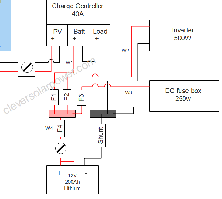
These are the resistors in the circuit:
- Cable connections: 10 (red) + 6 (black)
- 1 Shunt
- 1 battery switch
- 2 fuses
- 2 meter 35mm² cable (2AWG)
This is the formula for the entire battery to inverter circuit:
(0.000 06 ohm * 16) + 0.000 1 ohm + 0.002 ohm + (0.000 35 * 2) + 0.0001 ohm =
0,00096 + 0.0001 + 0.002 + 0.00070 + 0.0001 = 0.00196 ohm
If the current in the circuit is 100Amps then we become the following power loss over all the components:
100A² * 0.00196 Ohm = 100A * 100A * 0.00196 Ohm = 19.6 Watts of power loss.
The power loss will be dissipated as heat.
We can see that the battery switch has the most resistance, thus we must ensure that we get a good battery switch that if from a branded company. The lower-cost switches from non-branded companies have a much higher resistance.

I’m an off-grid enthusiast. I created this website to give clear and straight-to-the-point advice about solar power. I’m also the author of the book ‘Off-grid solar power simplified‘. Read more about me on my about page, check out my Youtube channel, or send me a message.