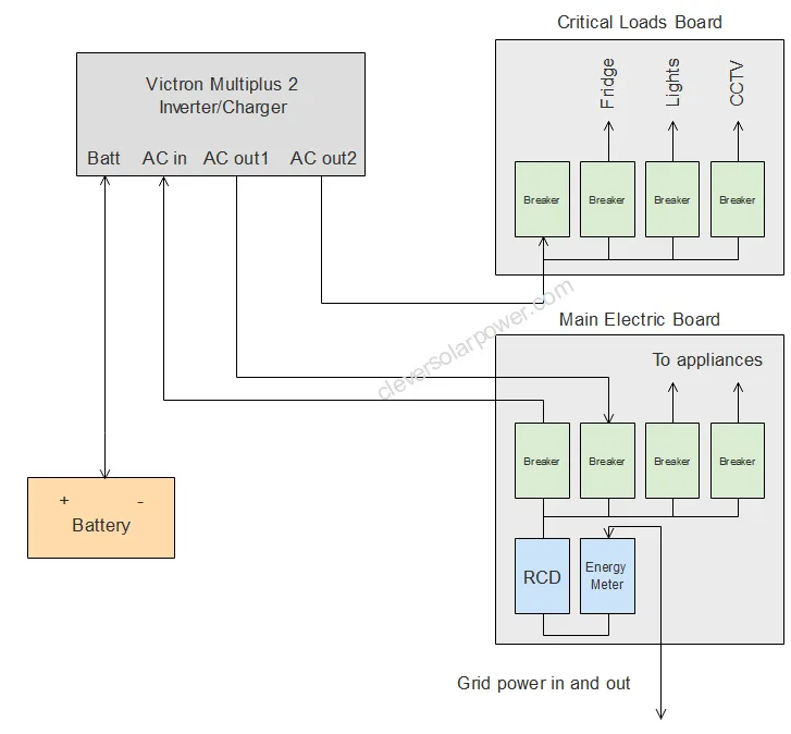
This diagram shows how to connect the Victron Multiplus 2 to your main distribution board.
Here’s a basic overview of how these connections are typically made:
- AC Input Connection:
- The AC input is used to connect the inverter to your grid or generator.
- Ensure the inverter is switched off and disconnected from all power sources (including batteries).
- Connect the live (L), neutral (N), and earth (ground) wires from your AC source to the corresponding terminals on the AC input of the MultiPlus II. The exact location and labeling of these terminals can vary, so refer to the manual for your specific model.
- AC Output 1 (Main Output):
- This output is used for your primary AC loads. It is only active when AC input is available. This is to protect servicemen from electric shock when they are working on the lines.
- Connect the live, neutral, and earth wires from your primary AC loads to the corresponding terminals on AC Out 1.
- Ensure that the total load does not exceed the inverter’s capacity. The maximum power can be set in the multiplus.
- AC Output 2 (Auxiliary Output):
- This output is typically used for non-essential loads (or critical loads). It is powered by the inverter when there is no AC input and switches to the AC input source when available. This is not allowed to go to your main distribution board. It should only be used to feed a separate breaker box or sockets.
- Connect the live, neutral, and earth wires from your auxiliary AC loads to the corresponding terminals on AC Out 2.
- This output is powered by the inverter in the event of a grid failure.
- Safety Precautions:
- Always follow local electrical codes and standards.
- Use appropriate cable sizes to handle the expected current.
- Ensure all connections are tight and secure.
- Double-check polarity and grounding to prevent damage to the inverter and connected devices.
- Testing:
- Once all connections are made, you can power up the system following the startup procedure outlined in the manual.
- Verify that the inverter operates correctly and that all connected loads are functioning as expected.
Remember, this is a general guide. For specific instructions, including diagrams and detailed steps, refer to the Victron MultiPlus II manual or consult with a professional.

I’m an off-grid enthusiast. I created this website to give clear and straight-to-the-point advice about solar power. I’m also the author of the book ‘Off-grid solar power simplified‘. Read more about me on my about page, check out my Youtube channel, or send me a message.
Hi
What is the startup procedure for the victron multiplus 48V/8000VA.
I don’t find this in the manual.
Thanx you
Connect the battery with a pre-charge resistor.