Do you want to know the efficiency of a PWM charge controller?
It depends…
But generally, the efficiency of a PWM solar charge controller can be from 30% to 80%. This depends on several factors.
Let me show you how you can calculate the efficiency of your PWM charge controller.
There are many factors to consider to calculate the efficiency of your PWM charge controller.
These are:
- Solar panel voltage
- Battery voltage
How does a PWM charge controller work
The working principle of a PWM charge controller is easy to understand.
It cuts the voltage to the same voltage as the battery.
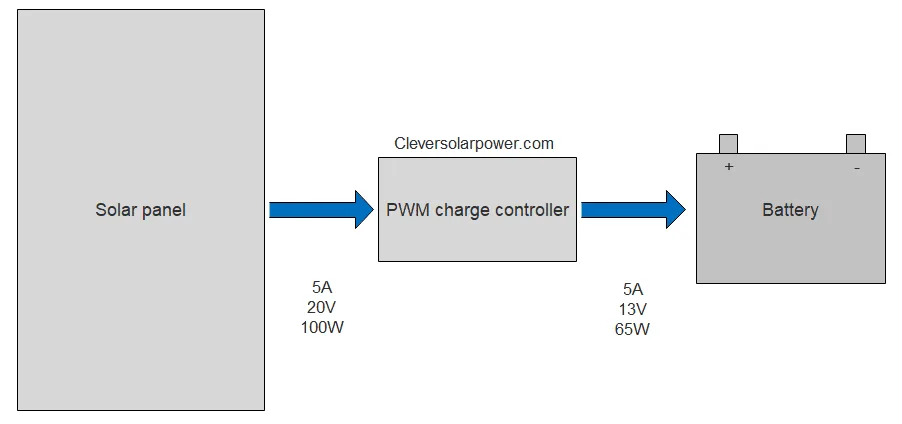
In the following diagram, we have a 20V solar panel and a 12V battery.
The PWM charge controller ‘cuts’ the voltage down from 20V to 13V to charge the battery. The remaining 7V is lost.The current stays the same.

Solar Panel Voltage
Let’s start with the most impactful of the three.
If we use the same example of 20V and 13V charging voltage, then we need to calculate the following:
input voltage – output voltage = voltage loss
Current * voltage loss = power loss
Using the example:
20V-13V = 7V loss
5A* 7V = 35W power loss
As you can see, the power loss will be 35 Watts. That is equal to:
(power loss/solar panel power)*100 = total percentage power loss
(35W/100W)*100 = 35% power loss
Battery Voltage
The input voltage of the PWM charge controller needs to be above the battery voltage.
For a 12V battery, we are going to use 18-22V solar panels
For a 24V battery, we are going to use 36-44V solar panels
Don’t use a PWM charge controller for a 48V battery. The losses will be too much. I don’t even think there are 48V PWM charge controllers.
An important aspect of the battery voltage and solar panel voltage:
You need to match your solar panels to your battery voltage.
Let’s explore this with an example:

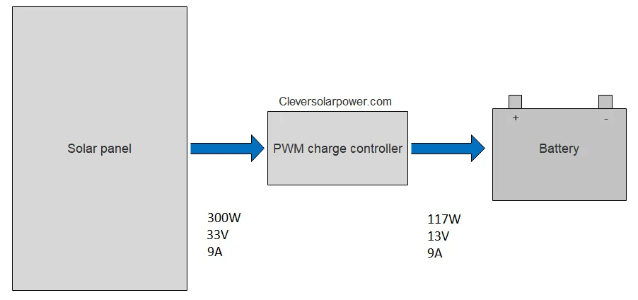
You have a 12V battery, a PWM controller, and a 300W solar panel with the following specifications:
- Power: 300W
- Current: 9A
- Voltage: 33V
Next, we apply the formulas:
33V-13V = 20V loss
9A* 20V = 180W power loss
As you can see, the power loss will be 180 Watts. That is equal to:
(180W/300W)*100 = 60% power loss
The efficiency of the PWM charge controller depends on the solar panel voltage and the battery voltage.
If we were to repeat the same calculations with a 24V battery, we would become the following:
33V-26V = 7V loss
9A* 7V = 63W power loss
As you can see, the power loss will be 63 Watts. That is equal to:
(63W/300W)*100 = 21% power loss
This is much better. If we have a high-voltage solar panel, we need to increase the battery voltage for the charge controller to be efficient.
If you would like to explore the best PWM solar charge controller, then read my article about it here.
FAQ
How can I calculate how many solar panels I can add to a charge controller?
I have written a whole article just about that. Read it here: How many watts can a PWM charge controller handle?
Can I use 24 volt solar panels to charge 12 volt batteries through PWM controller?
Yes, you can but you will have a lot of losses. It’s better to use a 12V solar panel for a 12V battery.
A 24 volt solar panel will have a voltage of 37V while a 12V solar panel will have a voltage of 18V.
Take a look at the previous example where I calculate the power loss of a 300W panel. The power loss can be as high as 60%.
[custom-related-posts title=”Related Posts” none_text=”None found” order_by=”title” order=”ASC”]

I’m an off-grid enthusiast. I created this website to give clear and straight-to-the-point advice about solar power. I’m also the author of the book ‘Off-grid solar power simplified‘. Read more about me on my about page, check out my Youtube channel, or send me a message.

Your description of a PWM baffles me. Your losses math show absolutely no improvement over a pure resistive voltage regulated system. I thought the whole idea of the Pulse Width Modulated system was to average the output by rapid on-off switching, thus for a moment there is the dropped voltage times ZERO amperage (Say 18V dropped to 12V at 5A would be a 6V reduction) so you would have 18V drop x 0A = 0 Watts lost in off cycle, and in the conductive cycle you would have full current flow of 5 amps but 0 volts dropped so 0V x 5A = 0 watts. Of course this would go into a RC network to provide a platform to pulse into and provide a place to average your output voltage to the desired output voltage. This being done at hundreds of thousands of times per second (aka frequency of the PWM) There would still be some losses across the resistive part of the RC network but nothing remotely like that of a passive analog voltage regulator.
Now, Iv only deducted this is the basis of a PWM, developed to SAVE from having the losses you are suggesting it does, making it no better then an analog, passive voltage regulator such as been used for many decades before the semiconductor.
Again, Im not an expert in PWM and MPPT systems but been in mostly radio electronics for nearly 60 years, ham radio, and retired commercial/industrial electrician.
You are right that the input will be cut, many times a second and the capacitors take the voltage spike. I have simplified how a PWM works, so most people will still get it.