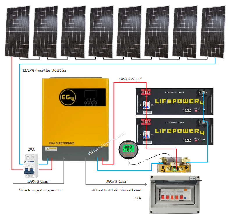
This system can be used for an off-grid property or an entire house if you heat and cook on natural gas. It will be compact because of the hybrid inverter. It has a high solar input voltage, so we can wire many panels in series. You can add a generator for winter.

Part list
- 8x 385W Solar panel
- EG4 3kW hybrid off-grid inverter
- 2x 48V Server rack battery
- 12AWG 100ft Solar PV cable
- 20A DC breaker
- Shunt battery monitor 350A
- 20ft 4AWG welding cable
- AC distribution box
- 32A AC breaker
- 10AWG wire
Description
This is a system which can be used for off-grid. It’s not possible to connect it to the grid because the inverter is not grid-interactive. You can connect the AC in to the grid to act as a battery charger but you cannot connect the AC out to the grid.
As a rule of thumb, we need to be able to recharge the whole battery in one day. One day averages 3 sunhours in Houston, Texas. Two lithium server rack batteries have a total storage capacity of:
51.2V ×100Ah ×2 batteries=10,240Wh
If we use solar panels rated for 385W, and we know that we have 3 sunhours per day on average, we can calculate how much one panel produces on an average day:
385W*3sunhours=1,155Wh per panel per day.
But we have to recharge 10,240Wh in a day, so we need this amount of panels:
10,240Wh/1,155Wh=8.8 panels -> let’s use an even number of 8 panels.
The hybrid inverter’s max input voltage is 500VDC. Let’s calculate the number of panels we can string in series.
The solar panel specs are:
- Pmax: 385W
- Operating Voltage (Vmp): 39.37V
- Operating Current (Imp): 9.78A
- Open-Circuit Voltage (Voc): 48.4V
- Short Circuit Current (Isc): 10.38A
500VDC/((48.4Voc ×1.25))=8 panels in series max.
The max current this hybrid inverter can charge the batteries with is 80A and the max input current is 18A.
8 panels rated at 385W each will give us a total of 3,080W at a voltage of 315V and 9.78A because a series connection adds up the voltage but the current stays the same.
The charging current to the battery is 3,080W/51.2V=60A. So this is correctly sized.
Let’s calculate the PV wire for this system if the solar panels are 100ft or 30m away from the PV input of the hybrid inverter using this voltage drop calculator (check my video about it here).
We need a minimum of 16AWG (1.5mm²) wire. Since no 16AWG PV wire is available, we will use 12AWG (4mm²).
This system has a shunt that monitors the battery’s state of charge in Ah of %. You have to calibrate it in the beginning, but that is easy.
The inverter can deliver a maximum of 3,000W on it’s output. With the inverter being 90% efficient, the power at the DC input will be more.
3,000W/0.9=3,333W at the DC input.
At a nominal battery voltage of 51.2V, we get:
3,333W/51.2V=65A
Applying the required safety factor of 1.25:
65A*1.25=81A will be drawn from the batteries. Since our two batteries are wired in parallel, each battery will deliver about 40A each.
Notice on the diagram that i have connected the positive on battery 1 and the main negative on battery 2. This is to help with even current distribution.
I have also added a shunt, you you can see the state of charge of the battery at any time.
We don’t have to fuse the wires going to the battery because there is already a DC breaker inside of the battery.
The breaker current is 125A, so we need to have a wire that can carry at least 125A, this is a 4AWG welding cable rated at 105°C insulation temperature.
We will use a 10AWG for the AC-in and AC-out connection to an AC distribution board.
Questions about this diagram? Send me an email here.