This article will educate you about grounding and bonding in your van.
First, we need to know some definitions.
Then, I will explain using a residual current device, the difference in electrical networks, and the neutral-to-earth link or NEM in inverter/chargers.
The last chapter will talk about practical applications.
Understanding Grounding Types and Bonding
There are different grounding types which we have to clear up:
- Earth: A direct physical connection to the Earth, typically using a copper rod, plate, or strip buried in the ground, or connected to water mains or pipes. This is not possible in a van or boat.
- Chassis Earth: Connection to a metal frame, like a vehicle or a boat’s metal hull.
- Ground: A common reference point in a circuit for measuring voltages.
There are differences between grounding and bonding:
- Grounding in Vans: In vans and other vehicles, true grounding (to the earth) is not feasible due to their mobile nature. Instead, the vehicle’s chassis is often used as a ground. The battery’s negative terminal is usually connected to the chassis, creating a common grounding point.
- Bonding in Vans: Bonding in vans involves connecting all metallic parts that are not intended to carry current to the chassis. This ensures that in the event of a fault, there is a safe path for the fault current to the ground (chassis), which helps in tripping the protective devices. These include inverters, charge controllers, and DC-to-DC transformers with a bonding terminal on the metallic case.
Understanding RCDs
We need to understand the function of an RCD before we can move on.
An RCD is there to protect people from electrocution. For an RCD to work, there must be two connections to Earth. One is at the power source, and one is at the appliance. This looks like this:
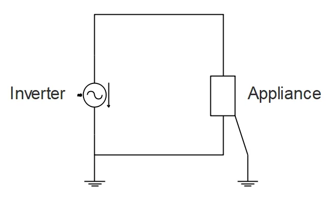
The inverter and earth (in this case, the vehicle’s chassis) are bonded to provide the path to chassis Earth. The appliance will also be bonded to the earth and return to the source through the chassis if there is a fault. This is a normal situation.
Now, when a fault occurs, let’s say the wire inside the appliance touches the case, then the current will flow parallel to the neutral and earth wires. There will now be two return paths to the source (the source is the inverter).
In this instance, the fuse will most likely melt because the resistance in the circuit is low.
I = U/R = 120V/2 Ohm = 60A -> blow the fuse
But when a human touches it, there is a higher resistance. The breaker doesn’t know that there is a human in the circuit. It just sees the resistance, thinking it’s an appliance.
I = U/R = 120V/1000 Ohm = 0.12 A -> will not blow the fuse
To protect the person, we will need to use a residual current device, also known as:
- Residual current circuit breaker (RCCB).
- Ground fault circuit interrupter (GFCI).
- Ground fault interrupter (GFI).
- Appliance leakage current interrupter (ALCI).
- Safety switch.
- Earth leakage device.
This device will detect the difference between the positive wire and the negative wire. it then knows there is a leakage current because the current going out and coming back is not the same. It will then interrupt the circuit.
A situation like that can be seen here:
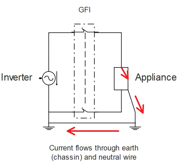
The GFI will break the circuit and stop the power flow through the system. You then come in and look for the fault in the system.
This can also happen to humans. Take a look at the following image:
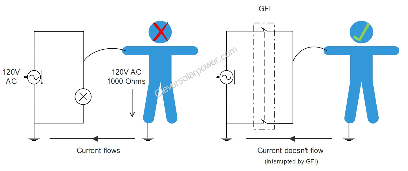
The first person will die because the current goes through the body parallel to the neutral wire. Current doesn’t take the path of least resistance; it travels in parallel with it.
The person is 1000 Ohms (wet hands), and the voltage is 120VAC. The current through the person and earth wire will then be:
I = U/R = 120V/1000 Ohm=0.12 Amps or 120 mA
The person on the right will still be alive because the GFI will detect the difference in current in the positive and negative wire and will trip in about 25ms after the person touches the appliance or live wire. The circuit will be interrupted, and the person will live. The current at which a GFI will trip can be 30mA (wet rooms) or 300mA (dry rooms).
For the GFI to work appropriately, there needs to be an earth at the power source.
This is why you must understand the current flow in a faulty circuit, which goes back through the earth to the source.
This ties in with the next chapter, the difference between IT and TT electrical networks.
Different Electrical Systems IT and TT
The following image shows the difference between an IT and a TT network.
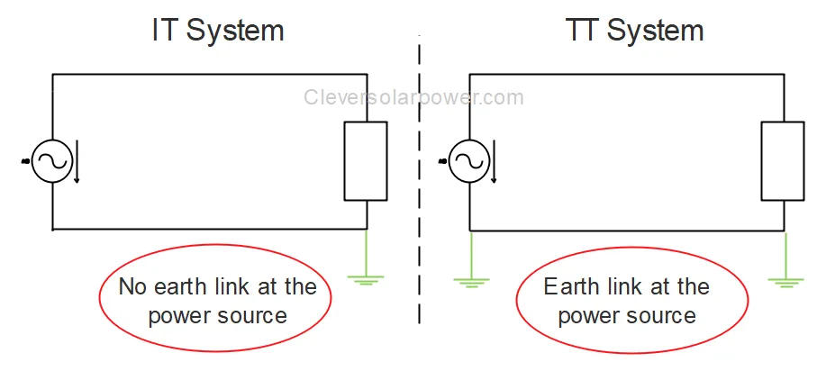
As previously discussed, we need to have an earth at the power generation source because that’s the only way the GFI will work.
We always need a TT network for the GFI to work.
Inverter/Charger and the Earth to Neutral link
Understanding the previous information is required to follow along in this chapter.
If we have an inverter/charger, we can have two modes. These are:
- Inverter mode (off-grid)
- Charger mode (shore connected)
Inverter Mode (off-grid or floating system)
When you are driving your van, it acts as an IT system.
As you already know, we need to convert the IT network to a TT network. We do this by adding an earth at the power generation side (the inverter/charger).
To make it possible for the electricity to flow back to earth, there needs to be a connection between the negative of the inverter and the earth of the system (the chassis).
Some inverters already have this connection made. Check your manual for this.
Below you can see a diagram of this. When the input relay is open (working off-grid), the relay between the earth and neutral is closed. This is the place where the neutral and earth are combined.
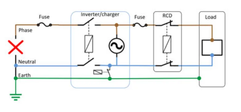
We can see shore power on the left, which is now disconnected. Then we can see the inverter charger relais which is opened because there is no power on the AC input terminal. This closes the neutral-to-earth link (NEM). Further, we have a fuse and the GFI, then the load.
The neutral-to-earth link is closed because there is no shore earth. This creates an earth on the power generation side, which we need in order for the GFI to work.
The system changes when we plug the inverter/charger into the grid.
Charger Mode (Grid-Connected)
When we plug the van in shore power, we have to break the neutral-to-earth link (NEM). At that time, we created an IT system that is unsafe. This is because the earth-to-neutral bond is broken and there is no earth at the power source.
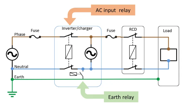
By using the earth wire from shore power we create a TT system again. Once the power is connected to the AC-input and the inverter is operating in charging mode, the neutral-to-earth link will be broken.
The earth relay or transfer switch does this for us automatically.
The following diagram shows this:
Practical Application
Some devices like chargers and inverters have negative and earth wires connected together on the inside of the device. If not, there will be an earth connection point. All these earth wires should go to the negative busbar or a separate grounding busbar.
Combining neutral and earth should only be done at one location. If you wire all the earth wires to the negative busbar, this is already done. If you have a separate earth busbar, make one connection from the earth busbar to the negative busbar.
You only need to connect to the chassis once from the grounding busbar or the negative busbar. Preferably use a bolt with locknut instead of a self-tapping screw because it can come loose due to vibrations. Clear the paint, drill the hole, use a ring terminal, and add the wire to the chassis. You should drill in the supporting column and not in the sheet metal.

I’m an off-grid enthusiast. I created this website to give clear and straight-to-the-point advice about solar power. I’m also the author of the book ‘Off-grid solar power simplified‘. Read more about me on my about page, check out my Youtube channel, or send me a message.