Making your own DIY busbars is easy. This article shows you how to make busbars, save money, and have more diverse connection points available.
Let’s talk about the functions of a busbar first:
A busbar is a distribution point in an electrical system. It consolidates multiple electrical connections into a single point, facilitating power distribution from and to various components like the battery, charge controller, inverter, and a DC fuse box.
1. Sizing
The size of the busbar must be adequate to handle the total current that will flow through it. This involves calculating the total amperage from all connected components and ensuring the busbar can handle this without overheating.
Your inverter is most likely the biggest draw on your system. Let’s say you have a 8kW inverter and a 48V battery:
8000W/48V = 166A
Your busbar needs to be able to handle 166 Amps of current. We should multiply this by the safety factor of 125%. This then becomes:
166A * 1.25 = 207A
We need a busbar that can handle a current of 207Amps.
2. Material Selection
Busbars are typically made from conductive materials like copper or aluminum. Copper is preferred for its higher conductivity and resistance to corrosion, but aluminum is lighter and less expensive.
I always prefer to work with copper or tinned copper. Do not use copper-clad aluminum or CCA. If you use aluminum, you need to use another calculation method, which we will discuss later in this article.
3. Thickness of Busbar
Choose a thick enough copper or aluminum bar. The thickness and width will depend on the total current it needs to handle.
This is how you calculate the required thickness of a busbar.
Size = Height x Width (in mm)
Example:
This copper bar is for sale on amazon.com
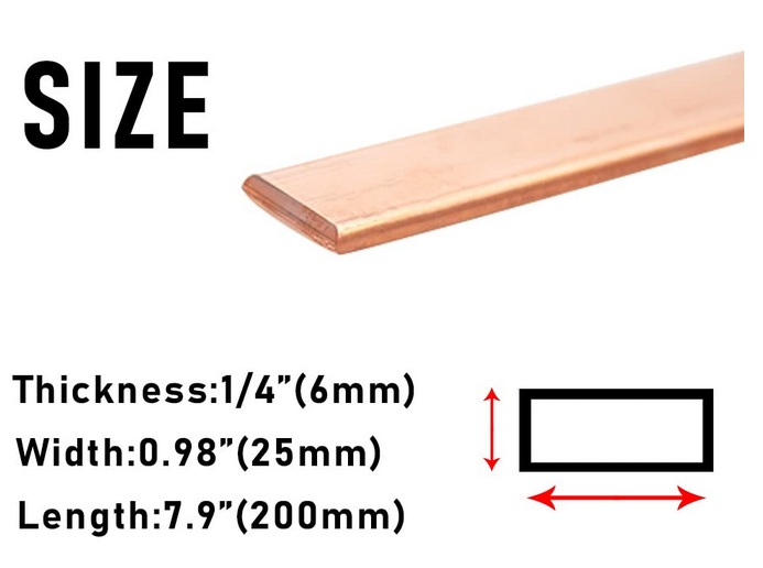
1/4 inch (6mm) * 1 inch (25mm) = 150mm²
We can compare this area to a wire. Because mm² is a surface calculation.
This is the same as a 150mm² copper wire. This is similar to three 50mm² cables because 3x50mm² is 150mm². 50mm² is equal to 1AWG (see table at bottom of page)
Therefore, the current this bar can carry is equal to the same current 3x 50mm² or 3x 1AWG cables can carry.
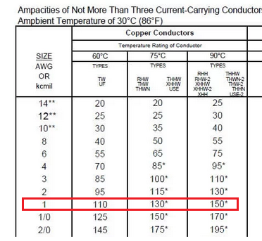
If we look at the NEC table for a 50mm² or 1AWG cable, we can see that it can carry 150Amps. So, if we multiply this by 3, we become 450 amps.
This busbar is suitable to carry 450Amps.
NOTE: If you have an aluminum busbar, then you should use the right column, which is suited for aluminum wires.
4. Insulation
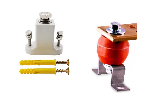
The busbar should be properly insulated to prevent accidental contact. Use non-conductive materials to mount the busbar and cover exposed areas.
These are called standoffs. You can buy them here or here (doesn’t come with bracket)
5. Connection Points
Drill holes for connection points, ensuring they are appropriately sized for the cables and bolts you will be using. It’s important to have a secure and low-resistance connection.
You can thread the holes after, but it’s not required. Holes will generally be M6 or M8.
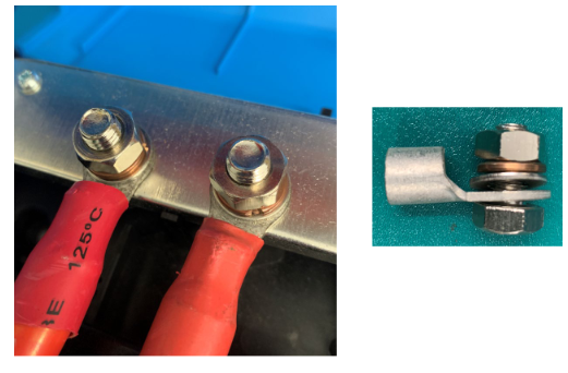
You should have the bolt upside down in the drilled hole of the busbar. This will have the least resistance. So it becomes:
- Bolt
- Busbar strip
- Lug
- Washer
- Lock washer
- Nut
Ideas
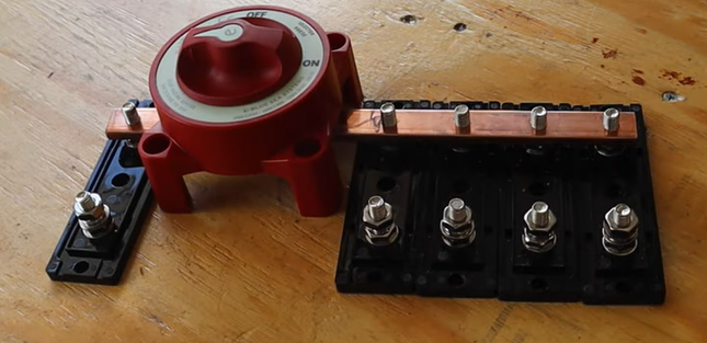
Here is an idea to have your own busbars made. This is a video from frugal factor who is making busbars that attach from the fuses to a battery switch. Link to video here.
There you have it! Your guide to making a DIY busbar.
If you have questions, feel free to ask in the comments below. I will get back to you ASAP.

I’m an off-grid enthusiast. I created this website to give clear and straight-to-the-point advice about solar power. I’m also the author of the book ‘Off-grid solar power simplified‘. Read more about me on my about page, check out my Youtube channel, or send me a message.
what sort of washers ,bolts and spring washers materials, EG only tensile grade 8.8 steel ? or what kind??
Nylon locknut, or spring washer + nut, or spring washer + nut + threadlock