Here is the diagram:
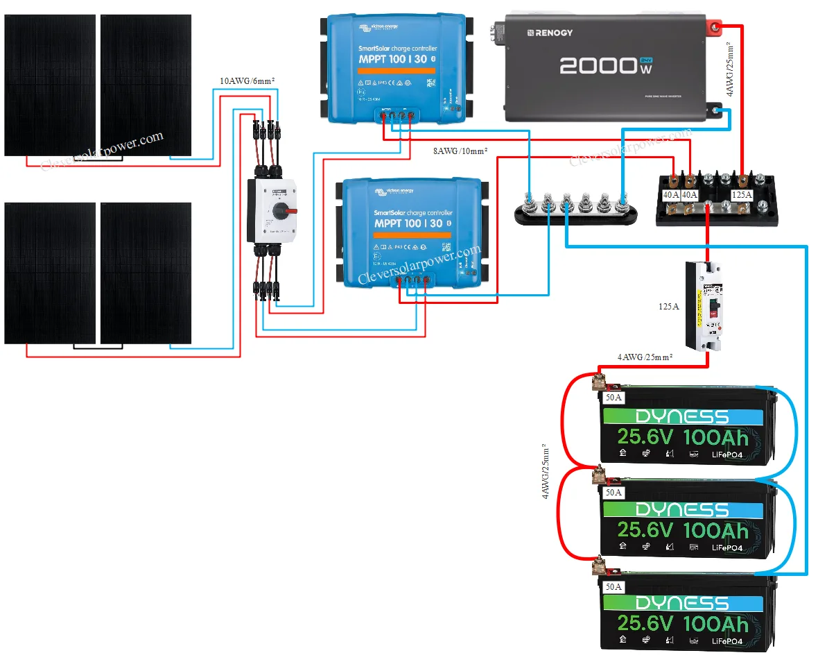
Parts
- 24V 100Ah Battery
- 100/30 MPPT Charge Controller
- 400W Solar panel
- 24V 2000W Inverter
- 125A Molded DC Circuit Breaker
- 50A MRBF Fuse
- MRBF Terminal
- Victron MEGA fuse busbar
- Negative busbar
- MEGA Fuses
- PV Cable
- DC Disconnect Switch
- Welding cable
Load Analysis
This is what this system can run if it’s located in Houston, Texas:
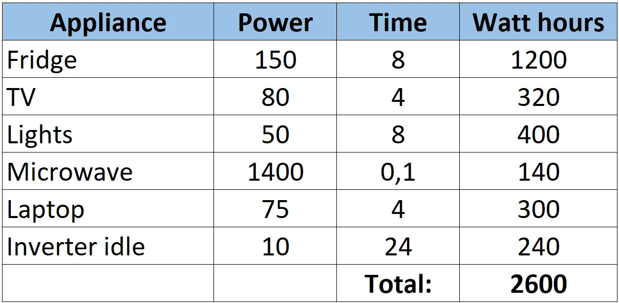
A total of 2,600Wh consumption per day and three days of autonomy gives us 7,600Wh of required battery capacity.
At a nominal battery voltage of 25.6V, we need a 305Ah 24V battery (7,600Wh/25.6V).
Next we go to PV watts and enter Houston, Texas as our location. We note down the latitude of 30° and enter it in my tilt angle calculator.
We go back to PV watts and enter the year-round tilt angle of 28 degrees. And we get 5.17 sunhours as an average in a year.
Next, we need to recharge the battery in one day.This might confuse some people, but we need to recharge three days of use in one day. That’s because we chose three days of autonomy. the amount of solar panels we need is: 7,600Wh/5.17 sunhours = 1,470W of solar power. We will use 4x 400W solar panels for a total of 1,600W.
Calculating cable and fuse sizes
Let’s say we have a 400W solar panel with the following specifications:
- Pmax: 400W
- Voc: 37.3V
- Isc: 13.68A
- Vmp: 31.0V
- Imp: 12.9A
In order to calculate the charge controller, we need to look at the Voc of the panel and multiply it by a safety factor for cold weather. That becomes 37.3V x 1.25= 46.6V. This tells me we probably need two charge controllers. Because we required 4 solar panels. 4 solar panels on one charge controller would be too much voltage (4 x 46.6V=187V). So i decide to split them up in groups of two, and we need two charge controllers. So 2 panels in series x 46.6V = 93V, so we can choose a 100V charge controller. And two panels in series gives us 800W, and at the nominal battery voltage of 25.6V, we have a current of 31.25A. This is perfect. A solar panel will rarely reach its rated power, and if it does, the charge controller clips the output to max 30A.
Let’s assume the solar panels are 45ft (14 meters) away from the charge controller. This is quite far so we need to do a voltage drop calculation.
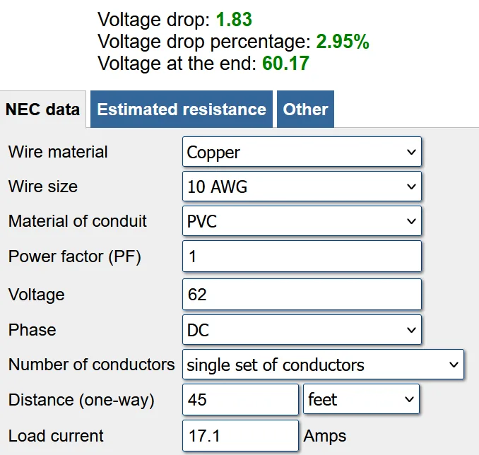
I’m using this voltage drop calculator. I enter a cable length of 45ft, and the voltage is Vmp multiplied by 2 panels. So that becomes 31V x 2= 62V. And the current is the Isc multiplied by a safety factor of 1.25. So that becomes 13.68 x 1.25=17.1A. As we can see from the image, we can use 10AWG or 6mm². Let’s check if this wire can carry the calculated current. To figure out the max current in this cable we need to add another safety factor for hot weather (because this is an outdoor cable). So the Isc x 1.56= 21.3A. And if we go look at the resources, a 10AWG cable can carry a max of 40A, so we are good here (PV cable is rated at 90°C).
You might ask, why do i need to do another current calculation while we calculated it before? Good question. Because the calculation for the voltage drop is under normal operations. So just the standard safety factor. But the wire diameter calculation need to use the outdoors safety factor as well, which is two times 1.25 for a total of 1.56.
The maximum current each charge controller can deliver is 30A, multiplying that with a safety factor of 1.25, we become 38A. The closes fuse size rounded up is 40A. A cable that can carry at least 40A is 8AWG or 10mm² cable.
I have three 25.6V 100Ah batteries in parallel. I recommend fusing every parallel battery, so i added MRBF fuses on each terminal. Let’s calculate the fuse size for these MRBF fuses after sizing the main breaker.
The maximum current going through the main breaker is: 2,000W/0.9 efficiency of the inverter = 2,222W on the DC input. Then we divide this by 24V (I decide not to use 25.6 because there will be a voltage sag when the battery is under load, and a lower number is better because you have more current at a lower battery voltage). So 2,222W/24V=92.6A, then multiplying by a safety factor, we get 116A. The closest breaker size rounded up is 125A, so we are using a 125A breaker, and a welding cable that can carry at least 125A is 4AWG or 25mm². The MEGA fuse going from the victron MEGA fuse busbar is also 125A and the cable is also 4AWG or 25mm².
Now back to the MRBF fuses. We calculated the inverter can draw a max of 92.6A spread over three batteries. That’s 92.6A/3 batteries = 30.8A per battery. Then I add the standard safety factor of 1.25 and another safety factor for batteries in parallel to have a combined safety factor of: 1.25×1.25=1.56. So 30.8Ax1.56=48A. I suggest using a 50A MRBF fuse, and the cable is still 4AWG or 25mm² because the cable has to carry the full current. If they were wired individually to a busbar, then we could have calculated our wire thickness according to the 50A fuse.